
OverDrive · Software
Real-time simulation of electric drives – physically exact, up to 32 times faster
OverDrive simulates motor, inverter and control with structure-preserving integrators. The results agree with LTspice, PLECS and Simulink – and OverDrive computes up to 32 times faster than conventional simulation tools. As an FMU, OverDrive runs directly in Simulink, CarMaker and other co-simulation environments.
OverDrive in numbers
Source: Persystems benchmark, Graz Smart Vehicle Forum 2025.
What OverDrive does differently
Fast, because the physics is right.
Conventional simulators buy accuracy with tiny time steps. OverDrive computes with integrators from geometric mechanics – they stay stable even with large steps and deliver results that are still correct after millions of time steps.
Extremely fast
Up to 32 times faster than conventional simulation tools. Validation of the inverter software runs twice as fast as real time – on a laptop, without a compute cluster.
Physically precise
Structure-preserving integrators conserve energy, charge and momentum – even with saturation and switching events. No numerical drift, no artificial damping.
Plug & play
Usable as an FMU according to the FMI standard in Simulink, CarMaker and other co-simulation environments. Existing models and parameters are reused – no redesign, no toolchain change.
Validation
Computed against established tools – and identical.
We continuously check OverDrive against LTspice, PLECS and Simulink: same circuit, same parameters, same excitation. Three examples from our benchmark of August 2026.
Half-bridge – Persystems vs. LTspice
Load current, sine with 100 A amplitude
Persystems LTspice
Half-bridge with MOSFET switches and freewheeling diodes driving a resistive-inductive load. Persystems and LTspice deliver the same load current.
Boost converter – Persystems vs. PLECS
Piecewise linear models, inductor and capacitor current
Persystems time steps PLECS
Every switching event is a kink in the curve. The Persystems time steps lie on the PLECS curve – including at the switching edges.
The stress test
Three-phase half-bridge with switching ripple
Three phases, run-up to 42 A, one switching event after another: this is where it shows whether a solver hits switching edges cleanly. The detail at 503.2 ms resolves the switching ripple of ±0.2 A – Persystems and PLECS lie on top of each other point by point.
Same circuit, same parameters, same excitation – and identical results.
Three-phase half-bridge – Persystems vs. PLECS
Phase currents during run-up, same circuit, same parameters
Persystems iu iv iw PLECS
Top: the run-up to about 42 A; bottom: the detail at 503.2 ms. The switching ripple of ±0.2 A is identical in both tools.
Integration
Into your toolchain in three steps.
Step 1
Reuse your model
Motor and inverter parameters from your existing simulations are reused. No rebuild, no duplicate model maintenance.
Step 2
Integrate the FMU
OverDrive comes as an FMU according to the FMI standard and runs in Simulink, CarMaker or your co-simulation environment – on the development PC, without a compute cluster.
Step 3
Validate
Test inverter software in the loop, tune controllers, run through fault cases and prepare HiL tests – in minutes instead of hours.
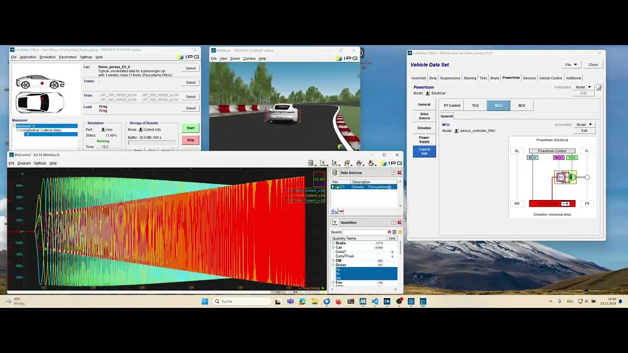
Playing the video transfers data to YouTube; nothing is loaded before that.
Video
OverDrive in CarMaker – live
A CarMaker demo vehicle with one electric motor on the front axle; the drivetrain consists of Persystems FMUs: motor, inverter and control run as OverDrive models directly inside the CarMaker simulation. The video shows the setup, the start and the result.
The same FMU also runs unchanged in Simulink and other co-simulation environments according to the FMI standard.
Key facts and use cases
What OverDrive can do.
Key facts
| Speed | up to 32× faster than conventional simulation tools |
| Validation | inverter validation 2× faster than real time |
| Integration | FMU according to the FMI standard – Simulink, CarMaker and other co-simulation environments |
| Numerics | structure-preserving integrators; energy, momentum and charge are conserved |
| Models | motor, inverter, control; switching events and saturation |
| Validated against | LTspice, PLECS, Simulink |
Fields of application
- Virtual function development – develop and test drive functions before the hardware exists
- Controller design – tune current controllers, speed and torque control on the physically exact model
- MiL / SiL / HiL – the same model basis across all test stages
- Inverter software validation – check firmware against the model of your own inverter
The physics behind it
Structure-preserving integrators
An electric drive is a mechanical-electrical system with conserved quantities. Classical integration methods discretize the differential equations – and in doing so violate exactly these conservation laws, step by step. Structure-preserving integrators start one level deeper – with the physics of the system itself. The result is a simulation that preserves the structure of the physical system: energy, momentum and charge are conserved, even over millions of time steps and even with large step sizes.
This is precisely what makes OverDrive fast: where conventional simulation tools have to fight drift with tiny time steps, OverDrive stays stable and precise with large steps. The foundations come from geometric mechanics – at Persystems they are a production tool.
━ OverDrive – structure-preserving ┅ conventional integrator
Contact
Want to see OverDrive on your own model?
License, evaluation or integration into your toolchain – write to us and tell us which drive you are simulating. You will get an answer straight from the engineering team.
| Product | OverDrive – real-time simulation of electric drives |
| Delivery format | FMU according to the FMI standard |
| Sales | sales@persystems.org |
| Phone | +49 941 462 974 40 |
| Company | Persystems GmbH, Regensburg, Germany |