
Inverter INV-60V-120A · Hardware
48 V inverter with field-oriented control – 6 kW, from 108 grams
Compact power electronics for drives from 17 to 60 V: field-oriented control, galvanically isolated CAN and PWM interfaces, DroneCAN, full telemetry and integrated protection functions – as case variant, embedded board or Aero variant. Developed and manufactured in Regensburg, Germany, adaptable to your application, hardware as well as firmware.
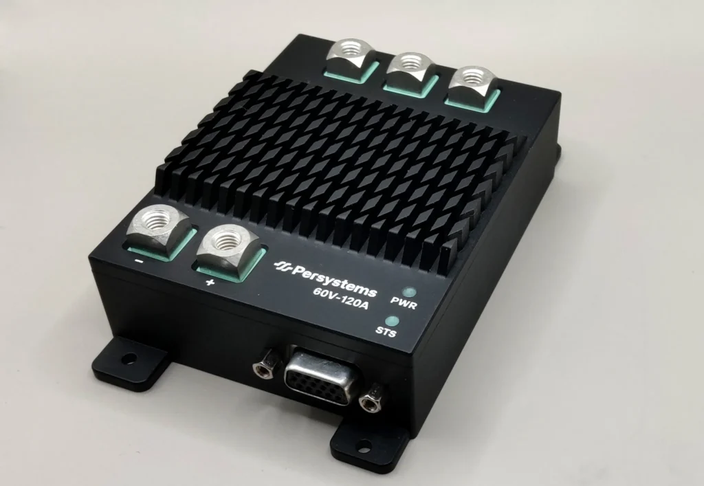
The inverter
INV-60V-120A: rugged, light, connected.
Designed for a very favorable power-to-weight ratio, high reliability and flexible integration – via CAN, DroneCAN or classic PWM.
INV-60V-120A · 6 kW
Technical data
One transistor pair per phase, 6 kW continuous power, 120 A continuous phase current (rms) – 337 grams in the case, 108 grams as Aero variant, on a footprint smaller than a smartphone. For drones, robotics and everything that demands little installation space and low weight.
| Continuous power | 6 kW (6.5 kW for 180 s) at 48 V |
| Voltage range | 17–60 V DC (48 V system) |
| Phase current | 120 A rms continuous (≈ 170 A peak), 135 A rms for 180 s |
| PWM frequency | 50 kHz |
| Variants | -C case (M6 studs, D-Sub 15 HD) · -E embedded board (Würth screw-in terminals, D-Sub 15 HD) · -A Aero variant (AWG 10 leads, Molex PicoBlade) |
| Dimensions | case 100.4 × 77.2 × 32.9 mm · boards 77 × 65 mm |
| Weight | 337 g case · 154 g embedded board · 108 g Aero (optional heat sink ≈ 90 g) |
| Cooling | air-cooled – heat-sink fins (case) or cooling plate / heat sink (boards); forced air for the full continuous rating |
| Ingress protection | IP-rated housing for the case variant on request |
| Interfaces | CAN 1 Mbit/s, galvanically isolated (PersyCAN, DroneCAN) · PWM/PPM, galvanically isolated · analog inputs |
| Position sensor | sin/cos, incremental encoder or sensorless |
Scope of delivery and integration
What you get
- INV-60V-120A inverter with field-oriented control and the Persystems firmware
- PC software for parameterization, firmware updates and fault diagnosis over CAN
- Protocol documentation for PersyCAN and DroneCAN – every message, every signal, every fault code; the technical documentation of the inverter (pin assignment, signal paths, fault handling, firmware update) is online at esc.persystems.org
- Adaptation of hardware and firmware to your application if the standard variant does not fit
- Dual-core variant: your own code on the second core of the controller, the motor control stays untouched – learn more
- Support from our engineering team with design and system integration
We develop and manufacture the inverter at our headquarters in Regensburg to the highest quality standards – and measure our drives on our own test bench.
Three variants
One inverter, three form factors.
The same power stage, the same firmware, the same ratings – 6 kW continuous, 120 A rms, 17 to 60 V. Form factor and connection concept differ: ready to mount in a case, as an embedded board for your system, or as the purpose-designed Aero variant for the air.
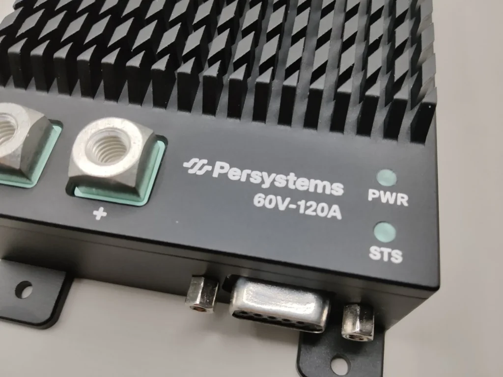
INV-60V-120A-C
Case variant
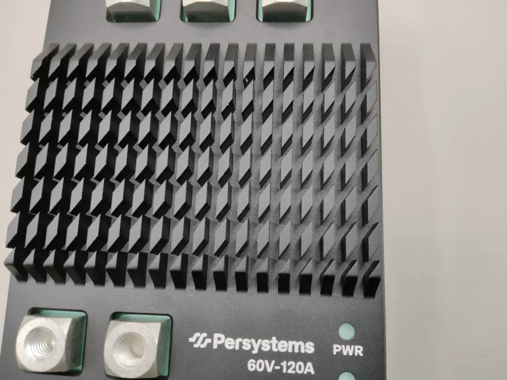
Anodized aluminum housing with cooling fins, M6 studs for DC and motor phases, D-Sub 15 HD for CAN, PWM/PPM, sensors and enable, status LEDs. For vehicles, machinery and test benches – everything that needs a rugged, ready-to-mount unit. IP-rated housing on request.
100.4 × 77.2 × 32.9 mm · 337 g
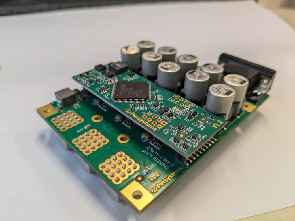
INV-60V-120A-E
Embedded board
The same electronics without a housing: Würth screw-in terminals for the power connections, D-Sub 15 HD for the signals, status LEDs. Mounted on a cooling plate or heat sink of your system – for integration into your own enclosures.
77 × 65 mm · 154 g
INV-60V-120A-A
Aero variant
A separate, weight-optimized board for drones and aviation: AWG 10 leads with gold contacts for DC and motor, Molex PicoBlade connectors for galvanically isolated CAN and PPM and the motor NTC. Optional heat sink of around 90 g.
77 × 65 × 33.5 mm · 108 g
The ratings of all three variants are in the datasheet; we will work out together which form factor fits your drive – tell us installation space, cooling and connection concept.
Control and interfaces
Field-oriented control, fully managed over CAN.
Field-oriented control
Speed and torque control with an inner Id/Iq current control loop, field weakening and MTPA. Rotor position sensorless from motor model and back EMF, or via sin/cos and incremental encoders. Setpoints arrive via CAN or PWM/PPM.
PersyCAN
Our CAN protocol for setpoints, parameters and telemetry: every 100 ms phase and DC current, DC voltage, speed, torque, MOSFET and motor temperature as well as controller and fault status. Parameterization, fault log and firmware updates run over the same bus.
DroneCAN
For flight controllers: esc.Status at 10 Hz, NodeStatus at 1 Hz, GetNodeInfo, up to 20 ESC indices per bus, fault states as health levels. The inverter is configured for PersyCAN or DroneCAN and can be switched during operation; our PC software reaches it via PersyCAN even when it is configured for DroneCAN – the stored configuration is retained.
PWM / PPM
Classic ESC control with signal monitoring: invalid signals, timeouts, inversion errors and noisy inputs are detected and reported. Arm/disarm via CAN or input.
PersyCAN · telemetry ● Example
0x1A000003 · 100 ms
Iph_Rms 29.6 A I_DC 30.0 A U_DC 50.2 V T_MOSFET 41.5 °C
0x1A00000C · 100 ms
RPM_act 5,980 RPM_target 6,000 TQ_act 2.150 Nm
0x1A000006 · 100 ms
Id −0.12 A Iq 41.9 A Id_trgt 0.00 A Iq_trgt 42.0 A
0x1A000008 · 100 ms
MotionCtrl ControlActive ErrorState OK
0x1A000013 · 100 ms
T_Motor 58.7 °C
In DroneCAN mode instead: esc.Status at 10 Hz, NodeStatus at 1 Hz, dynamic node allocation. Example values, not a measurement.
Example
What telemetry over PersyCAN looks like
Every 100 ms the inverter sends its operating data as CAN messages: phase and DC current, DC voltage, speed and torque, the temperatures of MOSFETs and motor as well as controller and fault status. Every message has a fixed ID and a documented byte layout – your ECU or your test bench reads it directly, without any intermediate software.
For flight controllers the inverter is switched to DroneCAN – it then sends esc.Status at 10 Hz and NodeStatus at 1 Hz, so ArduPilot and PX4 connect without any adaptation. The two protocols do not run at the same time; switching is possible during operation.
Protection functions
Protected – and traceable.
- Overcurrent, short circuit, overtemperature, undervoltage and sensor faults switch the drive into a safe state
- Safe Torque Off (STO) or Active Short Circuit (ASC) as a configurable reaction
- Signal monitoring of the PWM/PPM inputs: invalid, timeout, inversion, noisy
- Fault log retrievable over CAN – automatically on overcurrent, at any time on request
- Fault status in every telemetry cycle, additionally as a health level over DroneCAN (OK, Warning, Error, Critical)
- Firmware security: signed and encrypted updates with rollback protection – the security concept is being implemented now, learn more
Several inverters on one bus
Detected automatically, addressed automatically.
Several inverters starting with the same factory address? No problem: the PersyCAN discovery mechanism automatically assigns each of them its own CAN ID. Known devices get their previous address back after a restart – even if only one device was restarted.
Parameterization, firmware updates and fault diagnosis are handled by our PC software over the same CAN bus the drive is connected to.
Applications
From multicopters to mobile machinery.
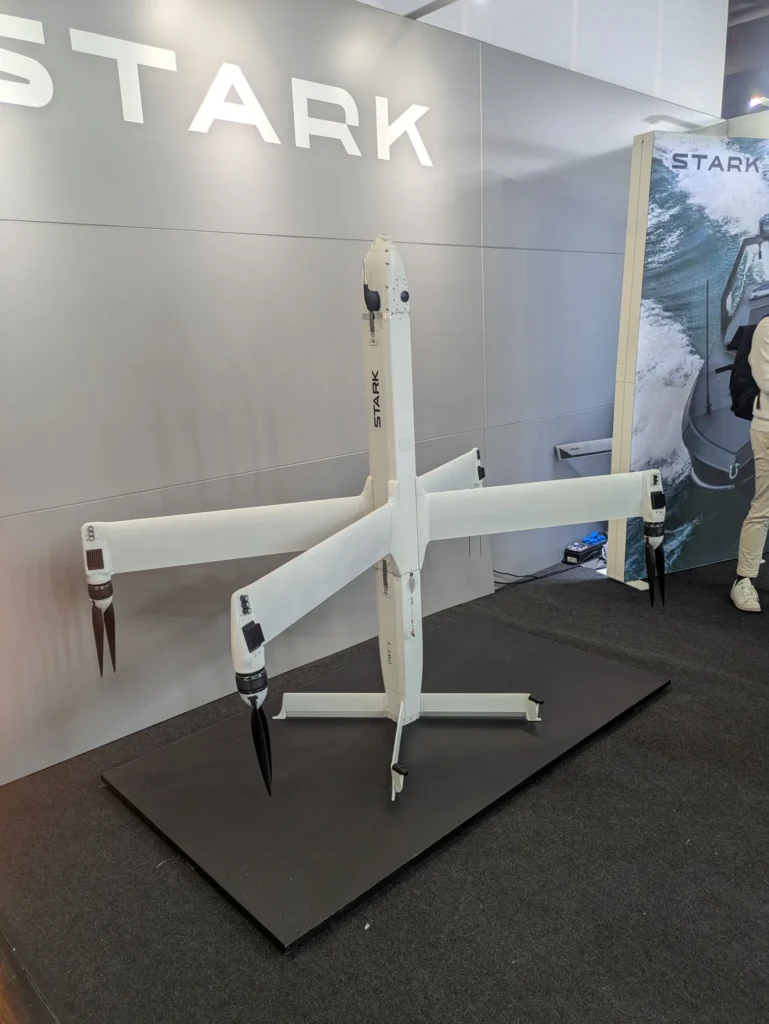
UAV · Drones
ESC with DroneCAN
Status telemetry at 10 Hz, dynamic node allocation and up to 20 ESC indices per bus – for multicopters, VTOL and heavy-lift drones.
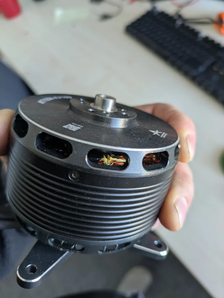
Industry · Robotics
48 V drives
Robotics, mobile machinery and industrial drives: compact, rugged, with speed and torque control and CAN connection to the machine network.
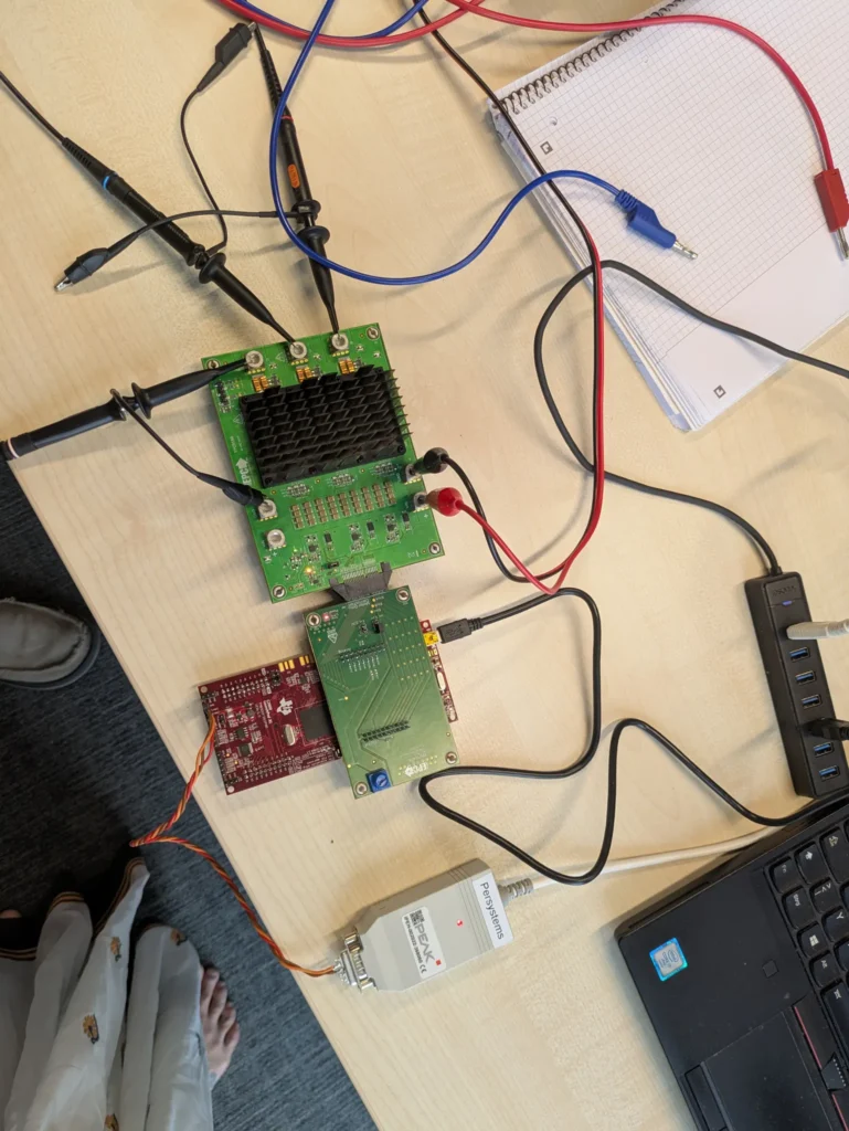
Development platform
Custom projects
We adapt hardware and firmware to your application. Our engineering team supports you with design and system integration – all the way to production readiness. One example: the GaN inverter INV-120V-40A with 99.125 % efficiency for a HAPS platform.
Quality
Tested on our own test bench.
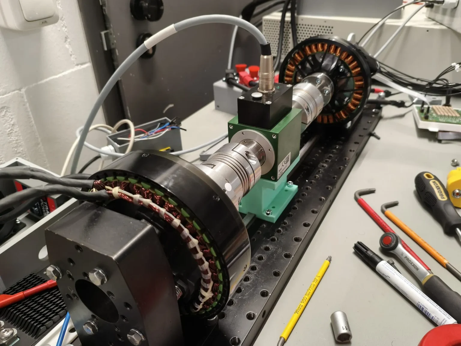
We measure inverters and motors on our own test bench in Regensburg – with power analyzer, torque transducer and continuous CAN logging. What we simulate, we verify by measurement: the same models that OverDrive computes with describe the inverters we build.
Developed and manufactured in Germany, to the highest quality standards.
Contact
Datasheet, sample or a conversation about your project?
Tell us which drive you are building – voltage, power, interface. You will get an answer straight from the engineering team.
| Product | INV-60V-120A inverter, 6 kW continuous power, three variants |
| Voltage | 17–60 V, designed for 48 V systems |
| Sales | sales@persystems.org |
| Phone | +49 941 462 974 40 |
| Company | Persystems GmbH, Regensburg, Germany |